

H20 Timber Beam (HT 20plus)
Click a photo to enlarge it.
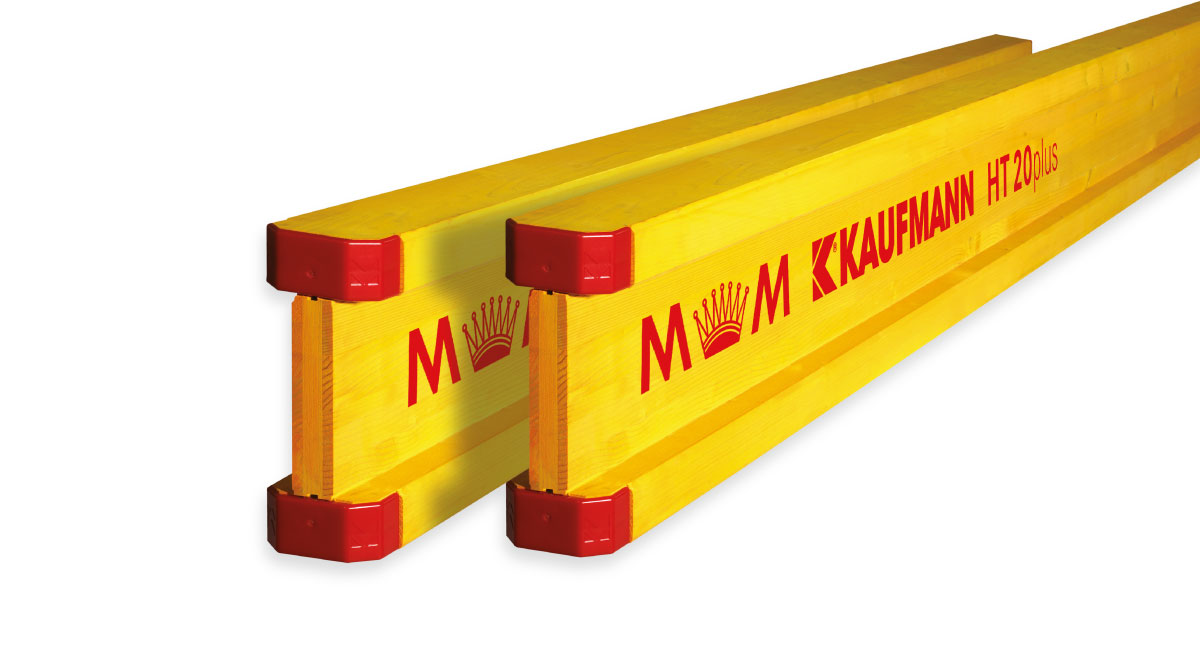
M&M Kaufmann HT 20plus H20 Timber Beam
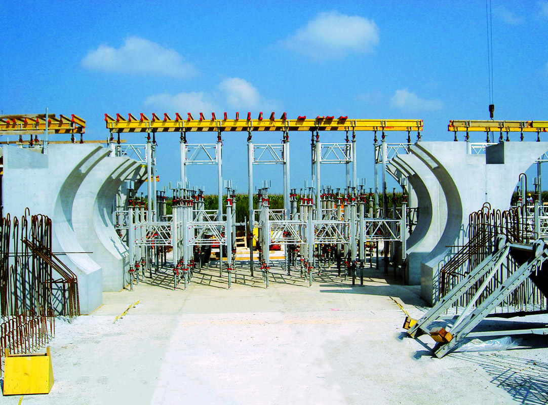
As a dealer of Mayr-Melnhof Holz (M&M Kaufmann), one of Europe's largest timber producers, we supply HT 20plus H20 timber beams. HT 20plus is an international brand used all over the world for its high number of reuses and reliable load capacity.
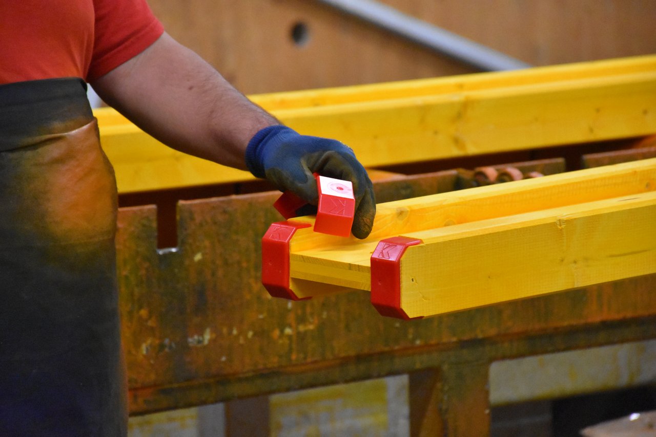
Quality raw material, precise processing and the proven plastic end-cap system give HT plus formwork beams a long service life. The web, made of a fully glued 3-layer solid wood panel, provides high load capacity in every climate. The flanges are made of machine strength-graded, finger-jointed timber; web and flanges are joined with an extremely strong finger joint.
Product standard
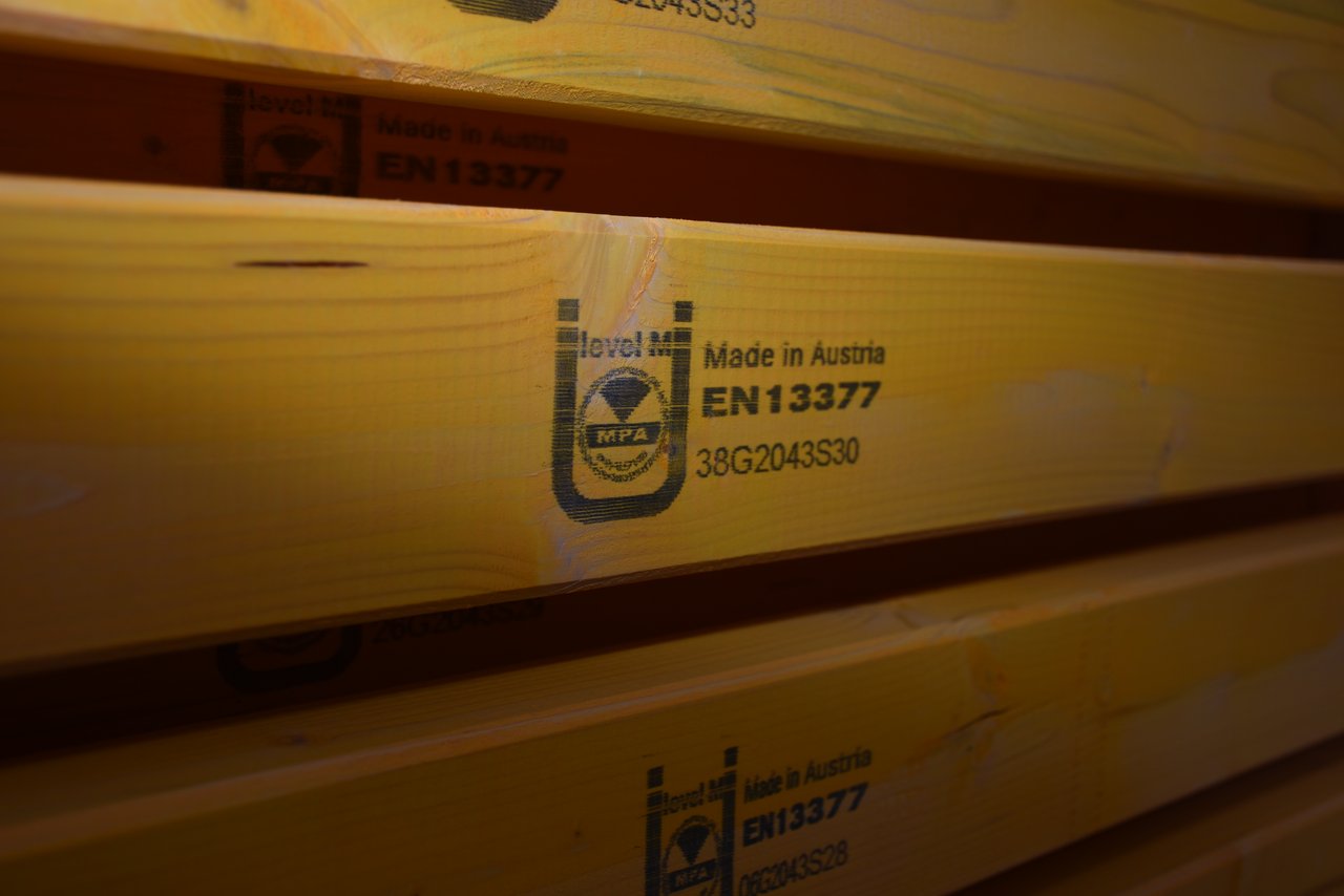
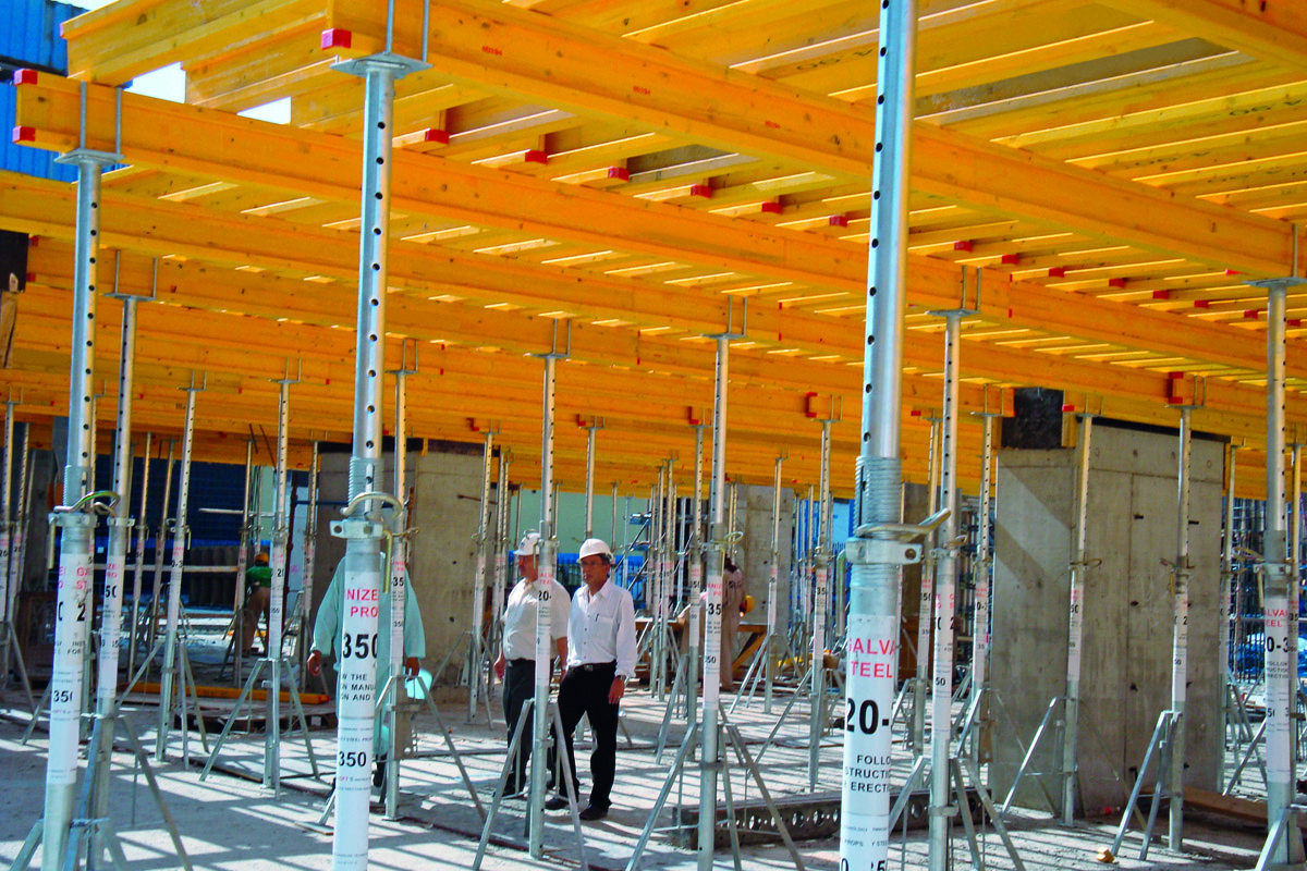
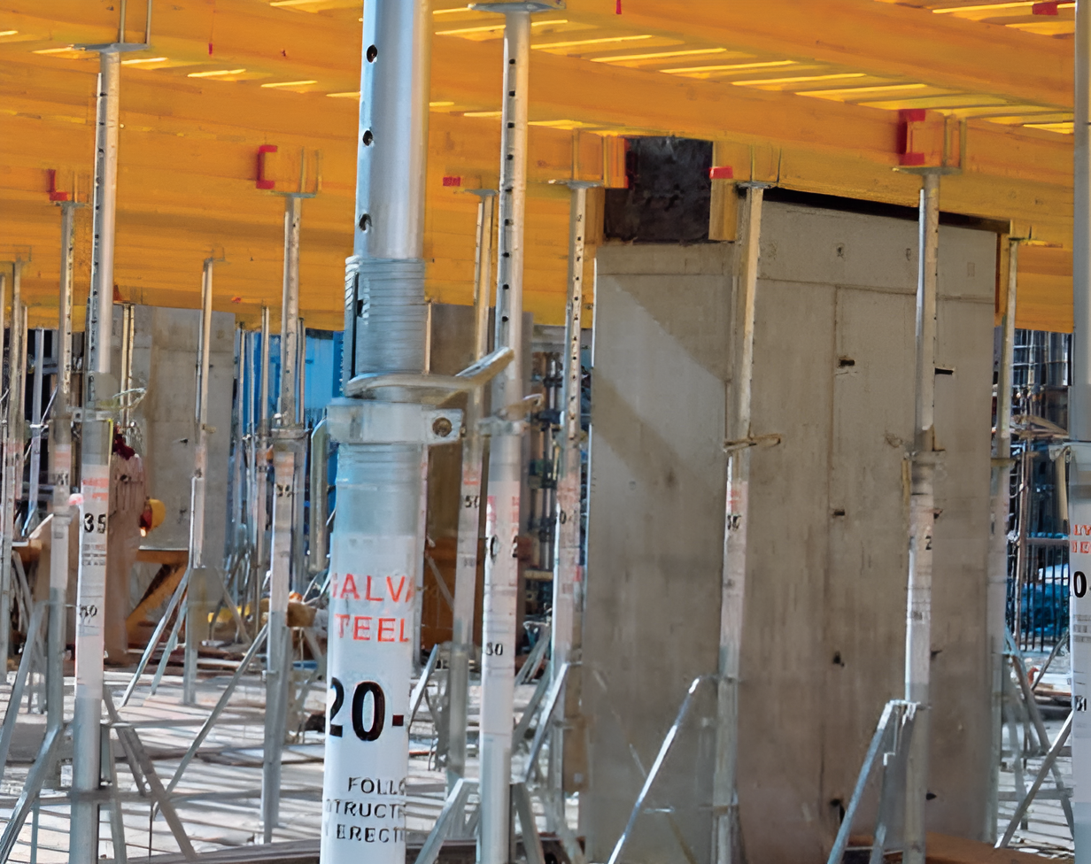
Industrially produced timber formwork beams are intended for use in falsework and formwork for concrete construction. They are loaded in the direction of the beam height. EN 13377 specifies the classification, requirements and test methods for formwork beams with heights of h = 16, h = 20 and h = 24 cm. In Germany, DIN EN 13377 applies together with DIN 20000-2; according to German regulations the beams are marked with the Ü mark (conformity mark).
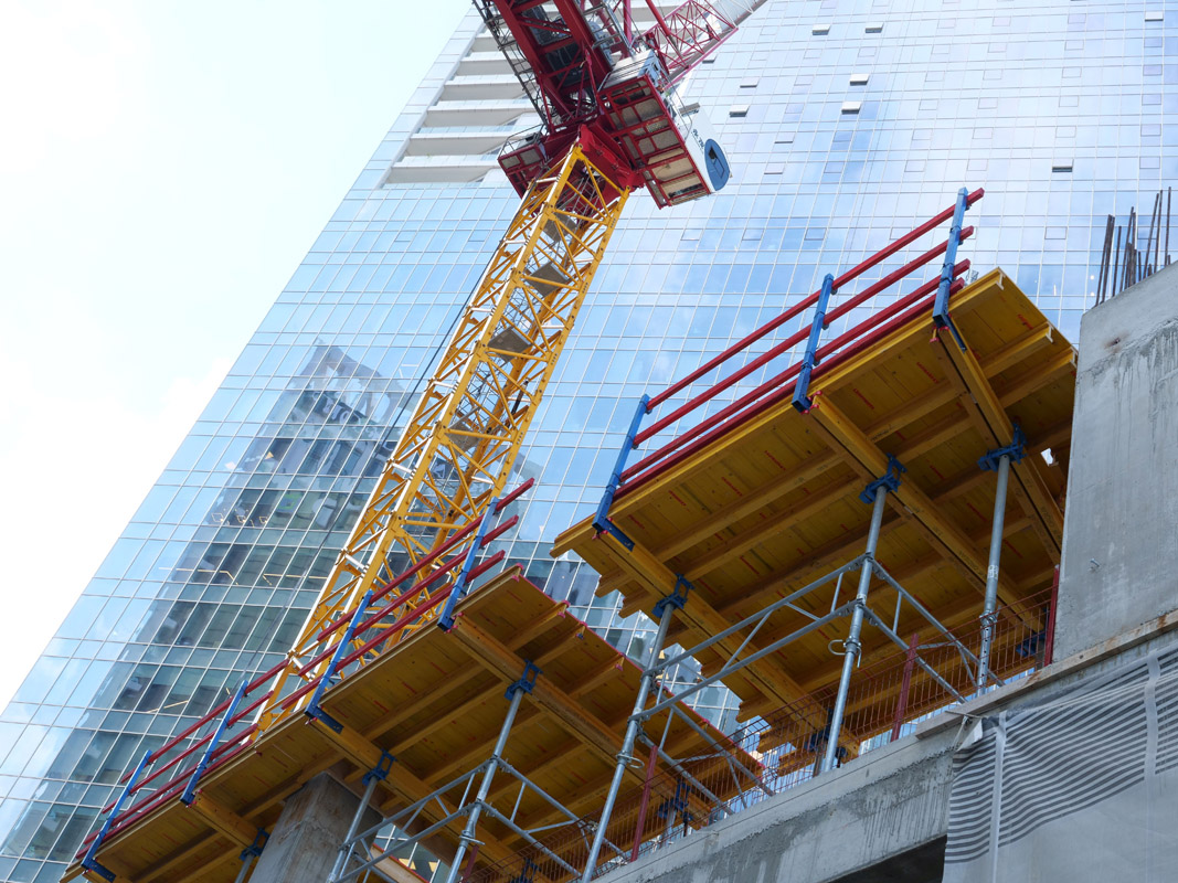
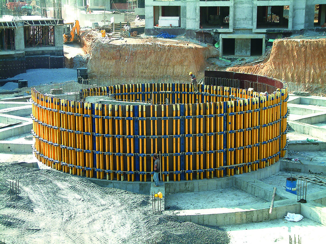
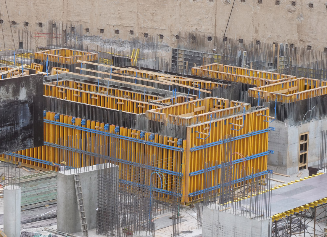
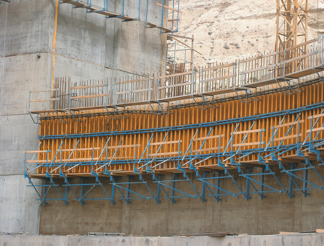
The images on this page are taken from the archive of our manufacturer Mayr-Melnhof Holz.

Technical Data
- Dimensions
- Beam height 200 mm (± 2.0 mm) · Flange height 40 mm (− 1.5%) · Flange width 80 mm (− 1.5%) · Web thickness 24 mm (± 0.5 mm)
- Lengths
- 1.80 / 1.90 / 2.00 / 2.45 / 2.50 / 2.65 / 2.90 / 3.30 / 3.60 / 3.90 / 4.20 / 4.50 / 4.90 / 5.90 / max. 10.00 m
- Weight
- 4.4 kg/m
- Packaging
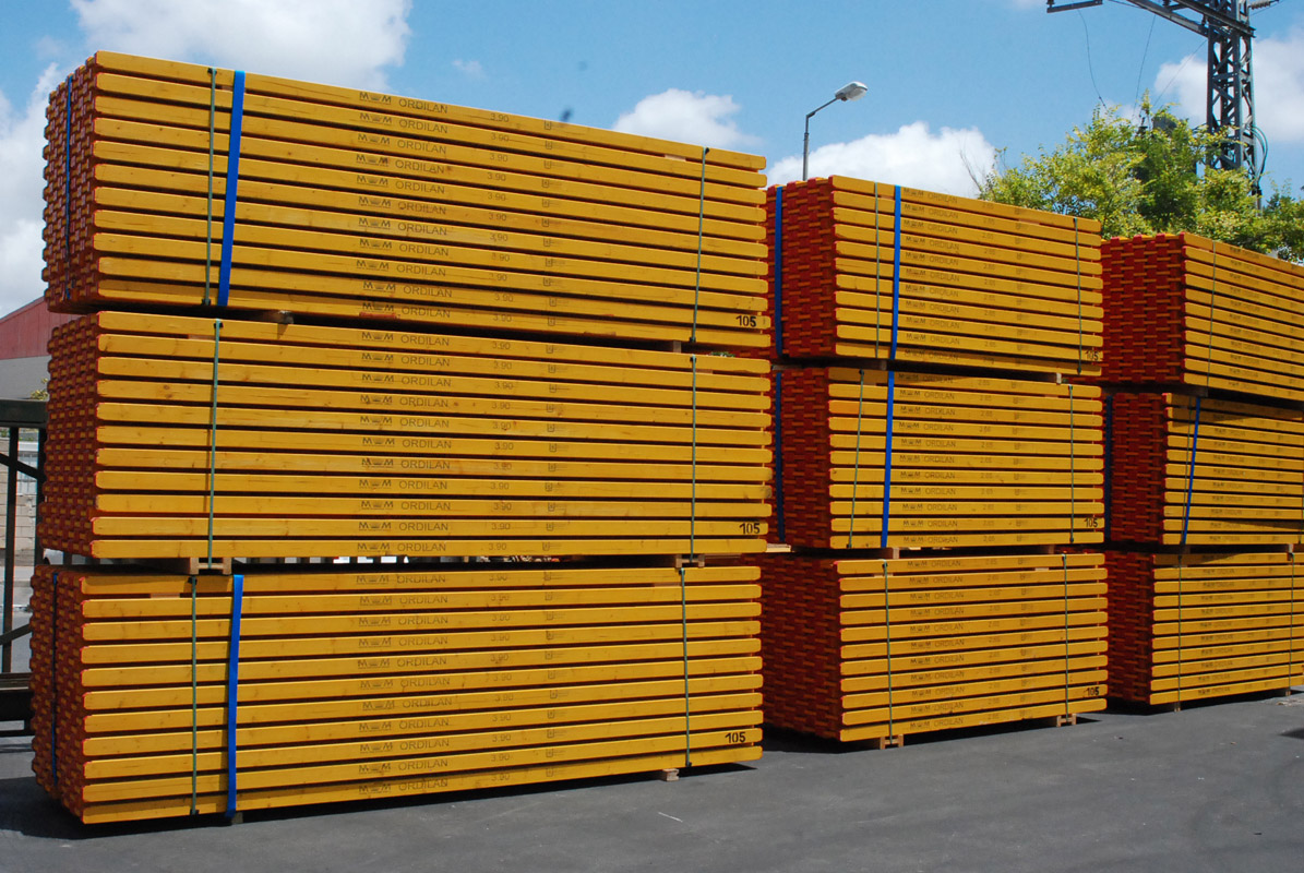
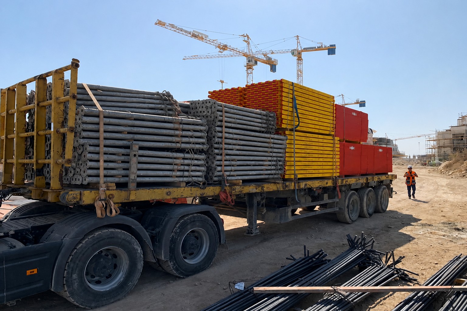
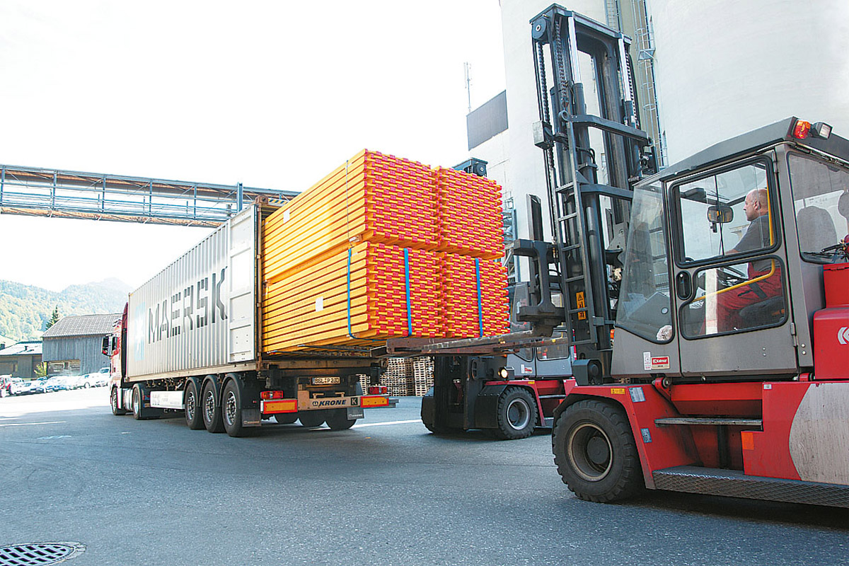
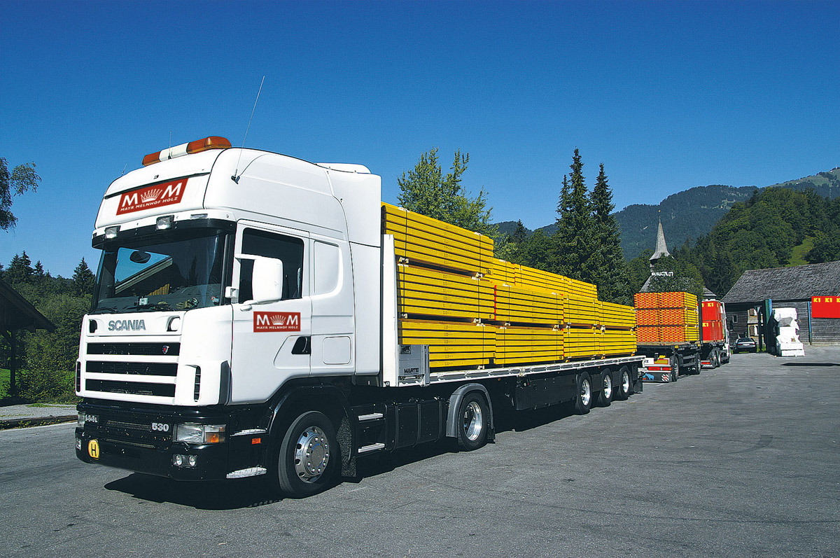
- Standard bundle: 100 pcs, container bundle: 105 pcs. Bundles are delivered on timber bearers, ready for site.
- Material
- Spruce and fir · Timber moisture 12% ± 3% · Melamine resin adhesive, EN 301 Type I · Fire class D-s2, d0
- Design Values (EN 13377)
- Vk = 23.9 kN (perm. Q = 11 kN) · Mk = 10.9 kNm (perm. M = 5 kNm) · Rb,k = 47.8 kN · EI = 486 kNm² · E flange = 11,000 N/mm² · E web = 6,700 N/mm²
HT plus Beam Family
Beams of different heights according to your needs (on request). Values are taken from the official Mayr-Melnhof Holz brochure.
| HT 12plus | HT 16plus | HT 20plus | HT 24plus | |
|---|---|---|---|---|
| Beam height | 120 mm | 160 mm | 200 mm | 240 mm |
| Flange height | 35 mm | 35 mm | 40 mm | 40 mm |
| Flange width | 65 mm | 65 mm | 80 mm | 80 mm |
| Web thickness | 24 mm | 24 mm | 24 mm | 24 mm |
| Weight | 2.7 kg/m | 3.1 kg/m | 4.4 kg/m | 4.9 kg/m |
| EI (bending stiffness) | 97 kNm² | 212 kNm² | 486 kNm² | 775 kNm² |
| Vk (shear, characteristic) | 15.3 kN | 18.4 kN | 23.9 kN | 28.2 kN |
| Permissible Q | 7 kN | 8.5 kN | 11 kN | 13 kN |
| Mk (moment, characteristic) | 4.4 kNm | 5.9 kNm | 10.9 kNm | 14.1 kNm |
| Permissible M | 2.1 kNm | 2.7 kNm | 5 kNm | 6.5 kNm |
| Rb,k (support reaction) | 29.4 kN | 36.8 kN | 47.8 kN | 56.4 kN |
| Length | max. 5.00 m | max. 8.00 m | max. 10.00 m | max. 10.00 m |
| Standard bundle | 144 pcs | 150 pcs | 100 pcs | 80 pcs |
| Quality control | WPK | WPK | WPK + MPA | WPK |
WPK = factory production control · MPA = external monitoring by the Materials Testing Institute Stuttgart. Permissible values according to EN 13377 Annex E (γm = 1.3, γF = 1.5, kmod = 0.9).
Load Table
| Slab thickness [cm] | Total load [kN/m²] | Table 1: Cross beamCross beam spacing [m] | Table 2: Yoke beamSelected yoke beam spacing [m] | |||||||||||
|---|---|---|---|---|---|---|---|---|---|---|---|---|---|---|
| 0.5 | 0.625 | 0.675 | 0.75 | 1 | 1.25 | 1.5 | 1.75 | 2 | 2.25 | 2.5 | 3 | 3.5 | ||
| Max. support width of cross beam = Max. yoke beam spacing | Max. permissible support width = Support spacing | |||||||||||||
| 10 | 4.60 | 3.64 | 3.38 | 3.29 | 3.18 | 2.89 | 2.64 | 2.41 | 2.23 | 2.09 | 1.97 | 1.87 | 1.59 | 1.37 |
| 12 | 5.12 | 3.46 | 3.21 | 3.13 | 3.02 | 2.74 | 2.50 | 2.28 | 2.11 | 1.98 | 1.86 | 1.72 | 1.43 | 1.23 |
| 14 | 5.64 | 3.30 | 3.07 | 2.99 | 2.89 | 2.62 | 2.38 | 2.17 | 2.01 | 1.88 | 1.73 | 1.56 | 1.30 | 1.11 |
| 16 | 6.16 | 3.18 | 2.95 | 2.87 | 2.77 | 2.52 | 2.28 | 2.08 | 1.93 | 1.79 | 1.59 | 1.43 | 1.19 | 1.02 |
| 18 | 6.68 | 3.07 | 2.85 | 2.77 | 2.68 | 2.43 | 2.19 | 2.00 | 1.85 | 1.65 | 1.46 | 1.32 | 1.10 | 0.94 |
| 20 | 7.20 | 2.97 | 2.76 | 2.69 | 2.59 | 2.36 | 2.11 | 1.92 | 1.75 | 1.53 | 1.36 | 1.22 | 1.02 | 0.87 |
| 22 | 7.72 | 2.88 | 2.68 | 2.61 | 2.52 | 2.28 | 2.04 | 1.86 | 1.63 | 1.42 | 1.27 | 1.14 | 0.95 | 0.81 |
| 24 | 8.24 | 2.81 | 2.61 | 2.54 | 2.45 | 2.20 | 1.97 | 1.78 | 1.53 | 1.33 | 1.19 | 1.07 | 0.89 | 0.76 |
| 26 | 8.76 | 2.74 | 2.54 | 2.48 | 2.39 | 2.14 | 1.91 | 1.67 | 1.44 | 1.26 | 1.12 | 1.00 | 0.84 | 0.72 |
| 28 | 9.28 | 2.68 | 2.49 | 2.42 | 2.34 | 2.08 | 1.86 | 1.58 | 1.35 | 1.19 | 1.05 | 0.95 | 0.79 | 0.68 |
| 30 | 9.80 | 2.62 | 2.43 | 2.37 | 2.29 | 2.02 | 1.80 | 1.50 | 1.28 | 1.12 | 1.00 | 0.90 | 0.75 | 0.64 |
| 35 | 11.23 | 2.50 | 2.32 | 2.26 | 2.18 | 1.89 | 1.57 | 1.31 | 1.12 | 0.98 | 0.87 | 0.78 | 0.65 | 0.56 |
| 40 | 12.65 | 2.39 | 2.22 | 2.16 | 2.05 | 1.74 | 1.39 | 1.16 | 0.99 | 0.87 | 0.77 | 0.70 | 0.58 | 0.50 |
| 45 | 14.08 | 2.30 | 2.13 | 2.05 | 1.95 | 1.56 | 1.25 | 1.04 | 0.89 | 0.78 | 0.69 | 0.63 | 0.52 | 0.45 |
| 50 | 15.50 | 2.23 | 2.03 | 1.96 | 1.85 | 1.42 | 1.14 | 0.95 | 0.81 | 0.71 | 0.63 | 0.57 | 0.47 | 0.41 |
| 55 | 16.93 | 2.16 | 1.94 | 1.87 | 1.73 | 1.30 | 1.04 | 0.87 | 0.74 | 0.65 | 0.58 | 0.52 | 0.43 | 0.37 |
| 60 | 18.35 | 2.09 | 1.87 | 1.78 | 1.60 | 1.20 | 0.96 | 0.80 | 0.69 | 0.60 | 0.53 | 0.48 | 0.40 | 0.34 |
| 65 | 19.78 | 2.01 | 1.78 | 1.65 | 1.48 | 1.11 | 0.89 | 0.74 | 0.64 | 0.56 | 0.49 | 0.45 | 0.37 | 0.32 |
| 70 | 21.20 | 1.94 | 1.66 | 1.54 | 1.38 | 1.04 | 0.83 | 0.69 | 0.59 | 0.52 | 0.46 | 0.42 | 0.35 | 0.30 |
| 75 | 22.50 | 1.89 | 1.56 | 1.45 | 1.30 | 0.98 | 0.78 | 0.65 | 0.56 | 0.49 | 0.43 | 0.39 | 0.33 | 0.28 |
| 80 | 23.80 | 1.83 | 1.48 | 1.37 | 1.23 | 0.92 | 0.74 | 0.62 | 0.53 | 0.46 | 0.41 | 0.37 | 0.31 | 0.26 |
| 85 | 25.10 | 1.75 | 1.40 | 1.30 | 1.17 | 0.88 | 0.70 | 0.58 | 0.50 | 0.44 | 0.39 | 0.35 | 0.29 | 0.25 |
| 90 | 26.40 | 1.67 | 1.33 | 1.23 | 1.11 | 0.83 | 0.67 | 0.56 | 0.48 | 0.42 | 0.37 | 0.33 | 0.28 | 0.24 |
| 95 | 27.70 | 1.59 | 1.27 | 1.18 | 1.06 | 0.79 | 0.64 | 0.53 | 0.45 | 0.40 | 0.35 | 0.32 | 0.26 | 0.23 |
| 100 | 29.00 | 1.52 | 1.21 | 1.12 | 1.01 | 0.76 | 0.61 | 0.51 | 0.43 | 0.38 | 0.34 | 0.30 | 0.25 | 0.22 |
Example: for a 30 cm slab with a cross beam spacing of 0.75 m, the cross beam can be supported at a span of up to 2.29 m; with a yoke beam spacing of 2.5 m, the yoke beam can be supported at a span of up to 0.90 m.
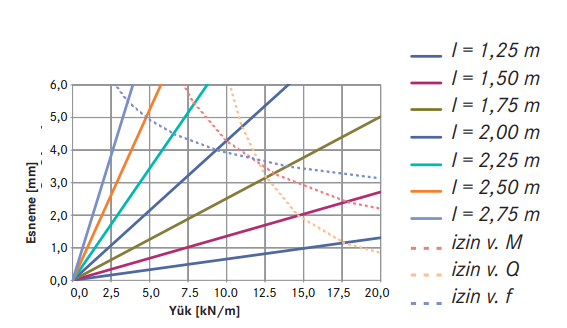
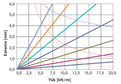
Design Charts
Why HT 20plus?
Strong Web
3-layer solid wood panel for structural outdoor use to EN 13353 SWP/3; high load capacity in continuous use in all climate zones.
Selected Solid Flanges
Made of quality, selected solid timber sections; machine strength-graded (at least C24) and finger-jointed.
Strong Joint
Flange and web are permanently joined with a finger joint.
Plastic End Cap
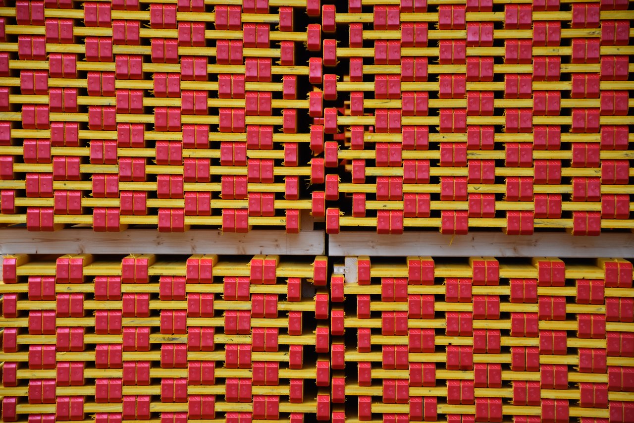
Protects the beam ends against splitting and clearly extends the service life of the beam.
Reusable
Proven load capacity even after many uses in every climate.
Clear Marking
Length and production code printed on the top of the flange.
Surface Protection
The whole beam is impregnated with a water-based coloured varnish; flanges are chamfered by about 4 mm.
Monitored Quality
Factory production control (WPK) and external monitoring by the Materials Testing Institute Stuttgart (MPA).