


01What Is Frame Shoring?
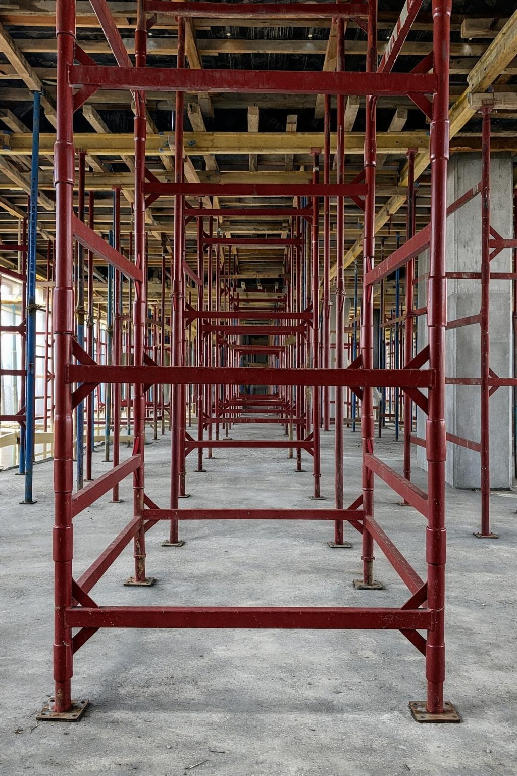
Frame shoring with spigot connections is a shoring system that rises as light H-shaped modules are stacked row by row on a square base frame. Towerframe is our version of this type: it is manufactured in our factory in Büyükçekmece and certified as a shoring tower to EN 12813.
Three main components carry the system. The spigot base frame is the square frame at the foot of the tower; the next component slides onto the tube ends at its four corners. The H module joins two short vertical tubes with a box section and takes its name from its shape. The base and top jacks set the tower on the ground and adjust its top level to the slab soffit.
The components are joined by push-fit ends called spigots: the end of one tube sits inside the other, with no wedge or coupler to tighten. In each row two H modules are fitted opposite each other, and the tower rises 50 cm with every row. The full component list in our product manual adds the brace, pin and split pin, H20 connector, top end module and, where needed, additional support members.
02Reading the Tower Spacing Table: From Slab to Tower
The table on the Towerframe product page gives three figures for twelve slab thicknesses from 20 cm to 100 cm: the load per square metre of slab, and the maximum clear distance that can be left between towers (Ls in the X direction, Lj in the Y direction). The first two columns describe the slab, the last two the layout of the towers on plan.
The load column is higher than the weight of the concrete alone. Using the 25 kN/m³ given for reinforced concrete in EN 1991-1-1, a 20 cm slab weighs 5.0 kN/m² in concrete alone, while the table gives 7.1 kN/m²; for a 100 cm slab the concrete is 25 kN/m² and the table 31.4 kN/m². The difference comes from the self-weight of the formwork and a factor covering the dynamic effect of pouring. These are not the only loads acting on shoring: effects such as wind, earthquake, and uneven pouring or concrete heaped in one place are also dealt with separately in the project-specific calculation. The table is therefore a starting value; the final load is determined by the conditions of the structure and the site.
Seven rows from the table:
| Slab thickness | Load | Clear distance in X (Ls) | Clear distance in Y (Lj) |
|---|---|---|---|
| 20 cm | 7.1 kN/m² | 300 cm | 215 cm |
| 30 cm | 9.8 kN/m² | 250 cm | 190 cm |
| 40 cm | 12.9 kN/m² | 250 cm | 160 cm |
| 50 cm | 16.0 kN/m² | 250 cm | 120 cm |
| 60 cm | 19.1 kN/m² | 200 cm | 100 cm |
| 80 cm | 25.4 kN/m² | 150 cm | 100 cm |
| 100 cm | 31.4 kN/m² | 100 cm | 75 cm |
As the slab gets thicker, the space between towers narrows: under a 20 cm slab a gap of 300 × 215 cm can be left between towers, while under a 100 cm slab this falls to 100 × 75 cm. The gap is not set by the tower capacity alone. Our product manual for the spigot type states that the tower layout is based on the capacity of the H20 beams and timber; in other words, the limit is usually set by the timber layer above the towers.
The distances in the table are achieved with double H20 primary beams in the short direction and secondary beams placed closer together as the slab gets thicker. Under thick slabs the secondary beams move closer and the primary beams work over short spans. That is why the table should be read with the tower and the beam layers above it as one system.
Get a quote for your project
Tell us about your facade or shoring requirement; our technical team will get back to you with an erection plan and a quotation.